
This message is used by an aids to navigation (AtoN) AIS station. It is generally transmitted autonomously at a rate of once every three minutes and should not occupy more than two slots.
|
Parameter |
Bits |
Description |
|---|---|---|
| Message ID | 6 | Identifier for Message 21 |
| Repeat indicator | 2 | Used by the repeater to indicate how many times a message has been repeated. |
| ID | 30 | MMSI number |
| Type of aids-to-navigation | 5 | 0 = not available = default; refer to appropriate definition set up by IALA; see Table below |
| Name of Aids-to-Navigation | 120 | Maximum 20 characters 6-bit ASCII, as defined in Table 47 “@@@@@@@@@@@@@@@@@@@@” = not available = default. The name of the AtoN may be extended by the parameter “Name of Aid-to-Navigation Extension” below |
| Position accuracy | 1 | 1 = high (<10 m) 0 = low (>10 m) 0 = default |
| Longitude | 28 | Longitude in 1/10 000 min of position of an AtoN (±180°, East = positive, West = negative 181 = (6791AC0h) = not available = default) |
| Latitude | 27 | Latitude in 1/10 000 min of an AtoN (±90°, North = positive, South = negative 91 = (3412140h) = not available = default) |
| Dimension/ reference for position |
30 | Reference point for reported position; also indicates the dimension of an AtoN. See Figure below. |
| Type of electronic position fixing device | 4 | 0 = Undefined (default) 1 = GPS 2 = GLONASS 3 = Combined GPS/GLONASS 4 = Loran-C 5 = Chayka 6 = Integrated Navigation System 7 = surveyed. For fixed AtoN and virtual AtoN, the charted position should be used. The accurate position enhances its function as a radar reference target 8 = Galileo 9-14 = not used 15 = internal GNSS |
| Time stamp | 6 | UTC second when the report was generated by the EPFS (0-59 or 60) if time stamp is not available, which should also be the default value or 61 if positioning system is in manual input mode or 62 if electronic position fixing system operates in estimated (dead reckoning) mode or 63 if the positioning system is inoperative) |
| Off-position indicator | 1 | For floating AtoN, only: 0 = on position; 1 = off position. NOTE 1 – This flag should only be considered valid by receiving station, if the AtoN is a floating aid, and if time stamp is equal to or below 59. For floating AtoN the guard zone parameters should be set on installation |
| AtoN status | 8 | Reserved for the indication of the AtoN status see {IEC 62288, Annex L} 00000000 = default |
| RAIM-flag | 1 | RAIM (Receiver autonomous integrity monitoring) flag of electronic position fixing device; 0 = RAIM not in use = default; 1 = RAIM in use see Table 50 |
| Virtual AtoN flag |
1 | 0 = default = real AtoN at indicated position; {For synthetic AtoN, also set Repeat Indicator field to 1} 1 = virtual AtoN, does not physically exist. |
| Assigned mode flag | 1 | 0 = Station operating in autonomous and continuous mode = default 1 = Station operating in assigned mode |
| Spare | 1 | Spare. Not used. Should be set to zero. Reserved for future use |
| Name of Aid-to-Navigation Extension | 0, 6, 12, 18, 24, 30, 36, ... 84 | This parameter of up to 14 additional 6-bit-ASCII characters for a 2-slot message may be combined with the parameter “Name of Aid-to-Navigation” at the end of that parameter, when more than 20 characters are needed for the name of the AtoN. This parameter should be omitted when no more than 20 characters for the name of the A-to-N are needed in total. Only the required number of characters should be transmitted, i.e. no @-character should be used |
| Spare | 0, 2, 4, or 6 | Spare. Used only when parameter “Name of Aid-to-Navigation Extension” is used. Should be set to zero. The number of spare bits should be adjusted in order to observe byte boundaries |
| Number of bits | 272-360 | Occupies two slots |
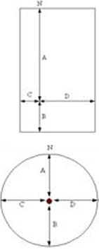
Reference point for reported position
|
|
Bits |
Bit fields |
Distance (m) |
|---|---|---|---|
| A | 9 | Bit 21 – Bit 29 | 0-511 511 = 511 m or greater |
| B | 9 | Bit 12 – Bit 20 | 0-511 511 = 511 m or greater |
| C | 6 | Bit 6 – Bit 11 | 0-63 63 = 63 m or greater |
| D | 6 | Bit 0 – Bit 5 | 0-63 63 = 63 m or greater |
(1) When using this figure for AtoN the following should be observed:
- For fixed Aids-to-Navigation, virtual AtoN, and for off-shore structures, the orientation established by the dimension A should point to true north.
- For floating aids larger than 2 m * 2 m the dimensions of the AtoN should always be given approximated to a circle, i.e. the dimensions should always be as follows A = B = C = D ≠ 0. (This is due to the fact that the orientation of the floating Aid to Navigation is not transmitted. The reference point for reported position is in the centre of the circle.)
- A = B = C = D = 1 should indicate objects (fixed or floating) smaller than or equal to 2 m * 2 m. (The reference point for reported position is in the centre of the circle.)
- Floating off shore structures that are not fixed, such as rigs, should be considered as Code 31 type from Table 74 AtoN. These structures should have their “Dimension/reference for position” parameter as determined above in Note (1).
- For fixed off shore structures, Code 3 type from Table 74, should have their “Dimension/reference for position” parameter as determined above in Note (1). Hence, all off shore AtoN and structures have the dimension determined in the same manner and the actual dimensions are contained in Message 21.
(2) When transmitting virtual AtoN information, i.e. the virtual/pseudo AtoN Target Flag is set to one (1), the dimensions should be set to A=B=C=D=0 (default). This should also be the case, when transmitting “reference point” information.
Type of aids to navigation
|
Nature |
Code |
Definition (Type of aid to navigation) |
|---|---|---|
| 0 | Default, Type of AtoN not specified | |
| 1 | Reference point | |
| 2 | RACON | |
| 3 | Fixed structures off-shore, such as oil platforms, wind farms. (NOTE 1 – This code should identify an obstruction that is fitted with an AtoN AIS station) |
|
| 4 | Emergency Wreck Marking Buoy | |
| Fixed AtoN | 5 | Light, without sectors |
| 6 | Light, with sectors | |
| 7 | Leading Light Front | |
| 8 | Leading Light Rear | |
| 9 | Beacon, Cardinal N | |
| 10 | Beacon, Cardinal E | |
| 11 | Beacon, Cardinal S | |
| 12 | Beacon, Cardinal W | |
| 13 | Beacon, Port hand | |
| 14 | Beacon, Starboard hand | |
| 15 | Beacon, Preferred Channel port hand | |
| 16 | Beacon, Preferred Channel starboard hand | |
| 17 | Beacon, Isolated danger | |
| 18 | Beacon, Safe water | |
| 19 | Beacon, Special mark | |
| Floating AtoN | 20 | Cardinal Mark N |
| 21 | Cardinal Mark E | |
| 22 | Cardinal Mark S | |
| 23 | Cardinal Mark W | |
| 24 | Port hand Mark | |
| 25 | Starboard hand Mark | |
| 26 | Preferred Channel Port hand | |
| 27 | Preferred Channel Starboard hand | |
| 28 | Isolated danger | |
| 29 | Safe Water | |
| 30 | Special Mark | |
| 31 | Light Vessel/LANBY/Rigs |
NOTE 1 – The types of aids to navigation listed above are based on the IALA Maritime Buoyage System, where applicable.
NOTE 2 – There is potential for confusion when deciding whether an aid is lighted or unlighted. Competent authorities may wish to use the regional/local section of the message to indicate this.